Enter the 3rd dimension
In the first article I showed how the Marching Cubes algorithm works in 2d.
To recap, you divide up the space into a grid, then for each vertex in the grid evaluate whether that point is inside or outside of the solid you are evaluating. There are 4 corners for each square in a 2d grid and there are two possibilities for each so there’s \( 2 \times 2 \times 2 \times 2 = 2^4 = 16 \) possible combinations of corner states for a given cell.
You then fill the cell with a different line for each of the 16 cases and the lines of all the cells will naturally join up. We use adaptivity to adjust those lines to best fit the target surface.
The good news is this works almost identically in the three dimensional case. We divide up the space into a grid of cubes, consider them individually, draw some faces in each cube, and they’ll join up to form the desired boundary mesh.
The bad news is that cubes have 8 corners, so there are \( 2^{8} = 256 \) possible cases to consider. And some of the cases are much more complicated than before.
The very good news is you don’t need to understand it all. You can just copy the cases I’ve put together and skip to the results section, forgetting about the whys and wherefores. Then start reading about dual contouring if you want a more powerful technique.
The whys and wherefores
Still here? Ok, you’re keen. I like that.
The secret is you don’t really have to assemble all 256 different cases. A lot of them are mirror images or rotations of each other.

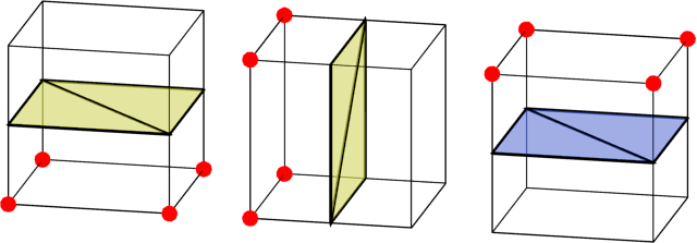
Here are three different cases for cells. The red corners are solid, and other are empty. In the first case, the bottom corners are solid and the top ones are empty so the correct way to draw a dividing boundary is to split the cell in half vertically. For convenience, I’ve coloured the outer side of the boundary as yellow and the inner side of the boundary blue.
The other two cases can be found simply by rotating the first case.
We have another trick to use:

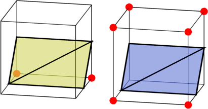
These two cases are inverses of each other – the corners of one are solid where the other is empty, and vice versa. We can easily generate one case from the other – they have the same boundary, just flipped.
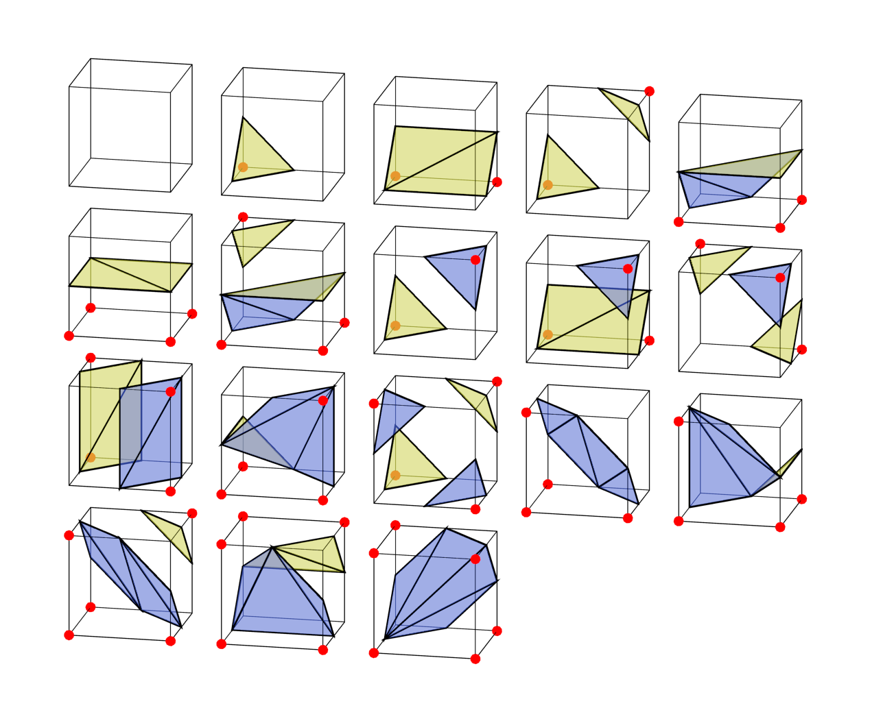
With that in mind, we only really need 18 cases from which we can generate all the rest.

Only sane man
If you check the wikipedia article or most tutorials for Marching Cubes, it says you only need 15 cases. What gives? Well, it’s true, the bottom three cases I’ve drawn in my diagram aren’t strictly needed. Here’s those extra three cases again, compared with using inverses of other cases to get a similar surface.
Both the 2nd and 3rd columns correctly separate the solid corners from the empty ones. But only when you consider a single cube in isolation. If you look at the edges on each face of the cell, you’ll see they are different for the 2nd column and 3rd column. The inverted ones won’t connect up properly with adjacent cells, leaving holes in the surface. After adding the extra three cases, all the cells will neatly join up.
Putting it all together
As in the 2d case, we can just run all cells independently. Here’s a sphere mesh made from Marching Cubes.
As you can see, the overall shape of the sphere is good but in places it is just a mess as very narrow triangles are generated. Read on to Dual Contouring, a more advanced technique with several benefits over Marching Cubes.