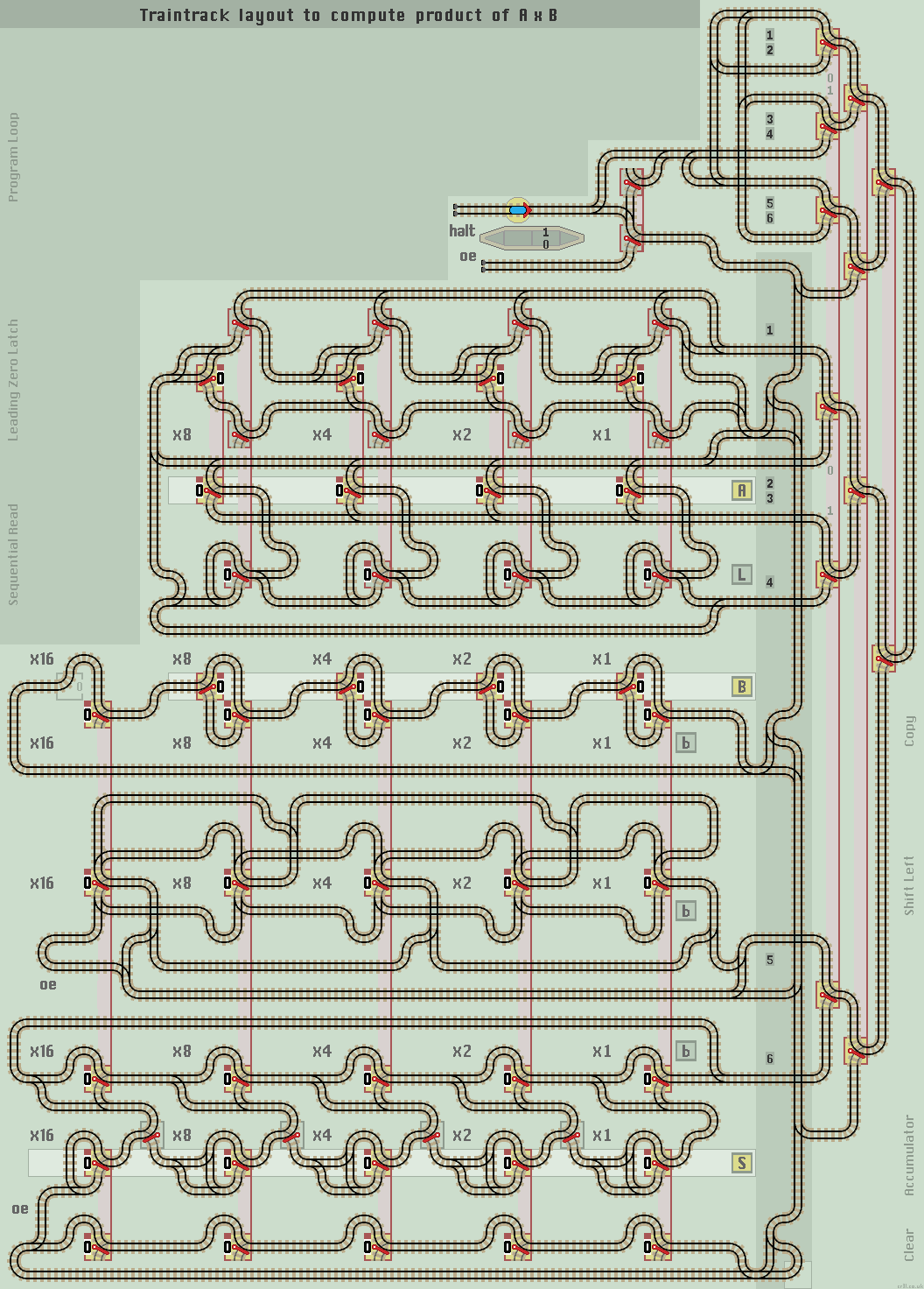
Multiplier Circuit
This circuit multiplies two binary numbers in registers A and B and outputs the result in register S. It uses a Shift Left and an Accumulator function to add successive multiples of 2. See Multiplier Basics at Wikipedia on how to multiply binary numbers.
The multiplier proceeds like this. First, the Clear & Error line:
- Sets latches to 1 for all leading zeros of register A and 0 thereafter.
- Copies register B into register B and sets x16 bit to 0.
- Clears the output Sum S register.
Then the main program loop cycles through these 4 steps:
- Read out the next data bit of register A.
(This also sets the next latch, -if all latches are 1 then halt). - If the data bit is a 1 then add register B to Sum register S.
- Check the latch register, (this does not set any latches). If all latches are set to 1 then halt.
- Rotate register B to the left (ie multiply by 2).
The main problem is preventing unnecessary shift lefts of register B. This not only wastes time, but the final shift left can create an overflow error. Hence the 'Leading Zero' function which checks for leading zeros in register A and halts the computation if all latches are set to 1.
We require 6 functions stacked in this order to make linking points easier:
- Leading Zero Latch function
- Sequential Read function
- Copy function (and set x16=0)
- Shift Left function
- Accumulator function
- Clear function (to reset S)
In the multiplier, the first two functions are combined. So if the latches are set to 11000 from the leading zero function, then when each digit in register A is read in turn, the latches will be set to 11001, 11011 and 11111. The latches are checked before each shift left, so the last setting of all 1's will halt the calculation before a final shift left occurs.
Multiplier Layout
Enter the two numbers to be multiplied into registers A and B. Read the computed output from register S.
|
| Click layout to pause/run train | Click points to switch 0/1 | Click start circle to reset train/points |
| Lazy points switch between upper 0 or lower 1 branch lines Trains arriving on a branch line switch the point to that line |
|
| Sprung points allow branch line trains to join the main line All main line trains go straight ahead and never 'branch off' |
Notes
- Multiplication is commutative, so AxB = BxA. A quicker calculation is obtained if the shorter number is entered into the A register, as there are fewer shift lefts to be carried out.
- If A=0, the calculation completes quickly. If B=0, then a series of shift lefts and additions are carried out on B, eventually giving the answer of 0. An extra function could be added, connected to the Clear & Error line, to halt if B=0.
- Both A and B are 4 bits long and the output register 5 bits long. This limits A and B to 7 and the output to 31. All registers can be increased by extending to the left. Usually, the output register is larger than the input registers.
- Register B is copied into register B. This preserves the value of input B and allows any extra bits due to a larger output register to be set to 0.
- There is no bypass switch as a Clear is needed before each calculation.
- The lower Clear & Error line return loop is truncated to save a couple of horizontal lines.
- The overflow error line from the adder is returned via the clear S register function to save one horizontal line.
- The halt return lines from the 'Leading Zero Latch' and the 'Parallel to Serial Converter' functions are combined to save space and also a Mux line.
- The shift left function fills the least significant bit with 0. Also, if the most significant bit is a 1, then a halt output stops the calculation immediately before a rotate left is carried out.
If the input registers A and B are linked together by extending the vertical link lines down from register A to register B, then the circuit acts as a 'square' maths function producing A x A.